
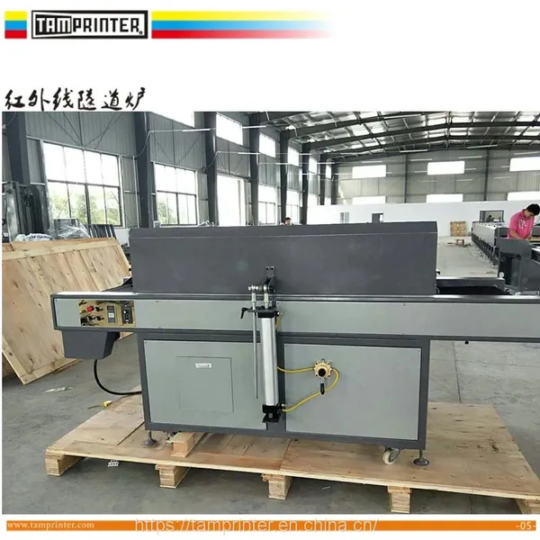
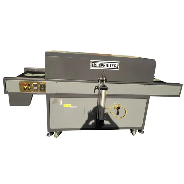
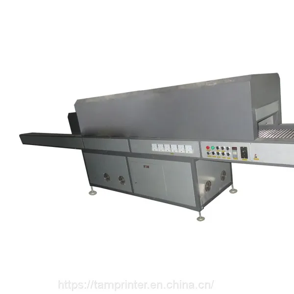
silicon sheet Flame treatment machine
Flame Treatment Machine
Catalog
Safety Instructions
1.1 Safety Regulations
1.2 Warning Labels (Photo)
1.3 NameplateSpecifications
2.1 Specification Table
2.2 Machine Noise Value
2.3 Machine Functions & Features
2.4 Main Components (Diagram)
2.5 Machine Dimensions (Diagram)Installation
3.1 Lifting Method (Diagram)
3.2 Installation Method (Diagram)
3.3 Installation & Leveling
3.4 Power Supply Requirement
3.5 External Power ConnectionOperation
4.1 Operator Position (Diagram)
4.2 Control Panel Description
4.3 Emergency Stop
4.4 Operation ProcedureMaintenance
5.1 Daily / Weekly / Monthly / Yearly Maintenance
5.2 Lubrication
5.3 Trouble Shooting
5.4 Scrap Disposal
5.5 Permissible Ambient Conditions
5.6 Storage ConditionsElectrical System
6.1 Safety Rules for Electrical Control System
6.2 Electrical & Pneumatic Diagrams
6.3 Electrical Parts ListPneumatic System
Consumables
1. Safety Instructions
1.1 Safety Regulations
1.1.1 General Safety
Know your machine.
Read this manual completely before operation. Understand the machine’s purpose, limitations, and potential hazards.Keep the work area clean.
Do not leave flammable items (e.g., rags) on the worktable.Keep unauthorized personnel away.
All visitors must maintain a safe distance.Do not force the machine.
Do not start the machine if the worktable is not returned to its home position. Operate within factory parameters. Any adjustment must be performed by qualified personnel or under our guidance.Use appropriate tools.
Do not force the machine or attachments to perform non‑intended tasks.Do not perform maintenance while the machine is running.
Disconnect power before repairing, changing attachments, or installing/uninstalling the motor.
Fire hazard.
Do not leave the machine running unattended.Silicon sheet placement.
Fully cover the mesh frame with the silicon sheet. Keep hands away from the flame.Maintain good footing and balance.
Anti‑slip floor recommended.Do not clean the machine while it is running.
Do not remove or alter warning labels. Replace any missing or covered labels.
1.1.2 Special Safety Rules
Keep away from both sides of the machine during operation.
Flame produces smoke. An exhaust hood is strongly recommended.
Wear a respirator, high‑temperature gloves, and other protective equipment.Before connecting to a stable 220V single‑phase power supply, check the main circuit. Verify that the switch, live wire, and neutral wire are correctly connected.
If any abnormality occurs or material is not fed in time during flame treatment, immediately brake or press the Emergency Stop switch.
2. Specifications
2.1 Specification Table
(Please insert your detailed specification table here)
2.2 Machine Noise Value
(Please insert measured noise value here)
2.3 Machine Functions & Features
Flame surface treatment for plastic/rubber parts
Automatic rotary worktable
Adjustable flame intensity and height
Touch screen control with manual/automatic modes
Emergency stop and motor brake for safety
2.4 Main Components (Fig.)
(Insert diagram of main components)
2.5 Machine Dimensions (Fig.)
(Insert dimension drawing)
3. Installation
3.1 Lifting Method (Fig.)
(Insert lifting diagram)
3.2 Installation Method (Fig.)
(Insert installation diagram)
3.3 Installation & Leveling
Place the machine on a solid, level floor. Adjust the leveling feet to eliminate any wobble.
3.4 Power Supply Requirement
Voltage: 220V AC, single phase, 50/60Hz
Stable power source with proper grounding
3.5 External Power Connection
Before connecting power, verify that the main switch, live wire, and neutral wire are correctly connected.
4. Operation
4.1 Operator Position (Fig.)
(Insert operator position diagram)
4.2 Control Panel Description
(Refer to Fig. 2 in original document)
Control panel (left to right):
| Component | Function |
|---|---|
| Touch screen | Human‑machine interface |
| Speed controller (knob + button) | Start/stop rotation; adjust table rotation speed |
| Pressure gauge & regulator | Controls flame gun air pressure (preset at factory; do not adjust unless necessary) |
| Ignition button | Manual ignition for flame adjustment before production |
| Emergency stop | Immediately stops all machine operation. To restart, rotate the button in the arrow direction until it pops up. |
| Start button | Starts the machine (parallel with foot switch) |
| Main power switch | Master power. Light on = powered. |
Touch screen interface (Fig. 3):
| Item | Function |
|---|---|
| Production counter | Displays current production quantity |
| Clear | Resets the counter to zero |
| Standby status | Shows current machine state |
| Start / Stop | Starts or stops the machine |
| Reset | Returns machine to standby state |
| Motor brake | Locks or releases motor brake |
| Single cycle / Continuous | Selects one‑stop‑per‑cycle or continuous operation |
| Return to home after cycle | Selects whether worktable returns to start position after each cycle |
| Parameter setting | Sets operation mode and action parameters |
| I/O monitoring | For programmer use only |
Parameter setting interface (Fig. 4):
Left 6 buttons: single manual actions
Right side: parameter settings
“Run page” returns to operation screen.
Gantry speed adjustment (Fig. 5):
Two knobs control forward and return speed of the gantry.
4.3 Emergency Stop
Press the red Emergency Stop button to immediately halt all machine movement.
To resume: rotate the button clockwise until it pops out, then re‑start normally.
4.4 Operation Procedure
Before power‑on inspection
Check machine status.
If the worktable is in the wrong position (as shown in Fig. 6 – e.g., caused by sudden power loss during operation):
Power on the machine.
Manually push the gantry inward into position.
Release the motor brake via touch screen.
Manually rotate the worktable to 90° relative to the machine (Fig. 7).
Then supply air and gas – the machine is ready.
Start‑up sequence (machine in correct position as Fig. 7, power & air on)
Adjust flame (Fig. 8):
Slightly open air (counter‑clockwise).
Briefly press Ignition button (air & gas solenoid valves open and ignite).
Slowly open gas (counter‑clockwise) to achieve required flame.
Press Ignition again to confirm. Flame adjustment done.
Adjust flame gun height using the two handwheels (left and right upper corners).
Set operation mode via touch screen.
Press Start button on control panel or step on foot switch to begin normal production.
In fully automatic mode: press Start or step on foot switch again to stop the machine and return to standby.
(Insert Fig. 1 – gas connection, Fig. 2 – control panel, Fig. 3 – touch screen, Fig. 4 – parameter screen, Fig. 5 – gantry speed knobs, Fig. 6 – wrong table position, Fig. 7 – correct table position, Fig. 8 – flame adjustment)
5. Maintenance
5.1 Daily / Weekly / Monthly / Yearly Maintenance
| Frequency | Action |
|---|---|
| Daily | Clean worktable and remove debris. Check for loose connections. |
| Weekly | Inspect gas hoses and fittings for leaks (soapy water test). |
| Monthly | Lubricate guide rails and rotary gears. |
| Yearly | Replace air/gas hoses if aged or cracked. |
5.2 Lubrication
Regularly apply lubricating oil to guide rails and rotary gears.
5.3 Trouble Shooting
(Please insert common problems and solutions)
5.4 Scrap Disposal
Dispose of the machine and all components according to local environmental regulations.
5.5 Permissible Ambient Conditions
Temperature: 0–40°C
Humidity: ≤85% (non‑condensing)
No corrosive gas or excessive dust
5.6 Storage Conditions
Dry, well‑ventilated area
Temperature: –10°C to 50°C
Protect from moisture and direct sunlight
6. Electrical System
6.1 Safety Rules for Electrical Control System
Only qualified electricians may access the electrical panel.
Disconnect main power before opening the electrical enclosure.
Do not modify internal wiring without authorization.
6.2 Electrical & Pneumatic Diagrams
(Insert electrical and pneumatic drawings)
6.3 Electrical Parts List
(Insert list of electrical components)
7. Pneumatic System
Medium‑pressure gas inlet (for LPG): copper nozzle at lower right (as shown in original Fig. 1).
Compressed air inlet: air preparation unit (3P compressed air).
Gas hose: use a red medium‑pressure regulator (type used for commercial kitchen stoves) and air hose, available at hardware stores.
8. Consumables
LPG (propane/butane)
Silicone sheet
Anti‑slip floor material (optional)
Lubricating oil for rails/gears
Replacement air/gas hoses

Contact Us
Recommended Products
-
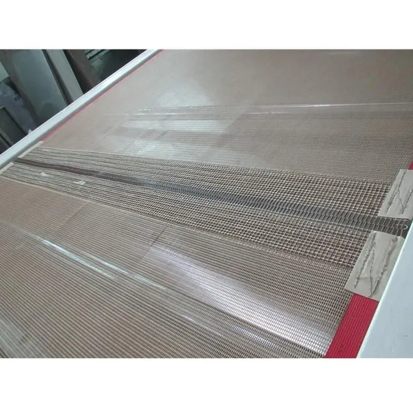
 Industry Food Grade Meta Teflon Conveyor BeltNegotiableMOQ: 1 Set
 -
Automatic Spot Coating Machine for Hotels, Retail, Food Shop, Printing Shops, Food & Beverage ShopsNegotiableMOQ: 1 Set
-
Automatic Screen Printing Machine,Coating Machine for Hotels, Retail, Food ShopNegotiableMOQ: 1 Set
-
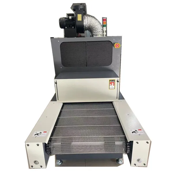
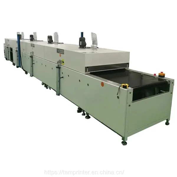
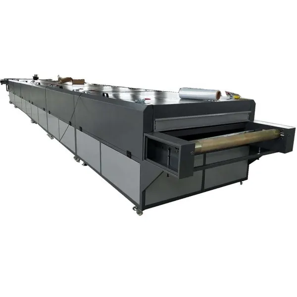
Infrared and Circulating Air Dryer Printing Ink Tunnel Oven MachineUS$ 6,880 - 7,500MOQ: 1 Set
-
Printing Ink Tunnel Oven MachineUS$ 6,880 - 7,500MOQ: 1 Set

-
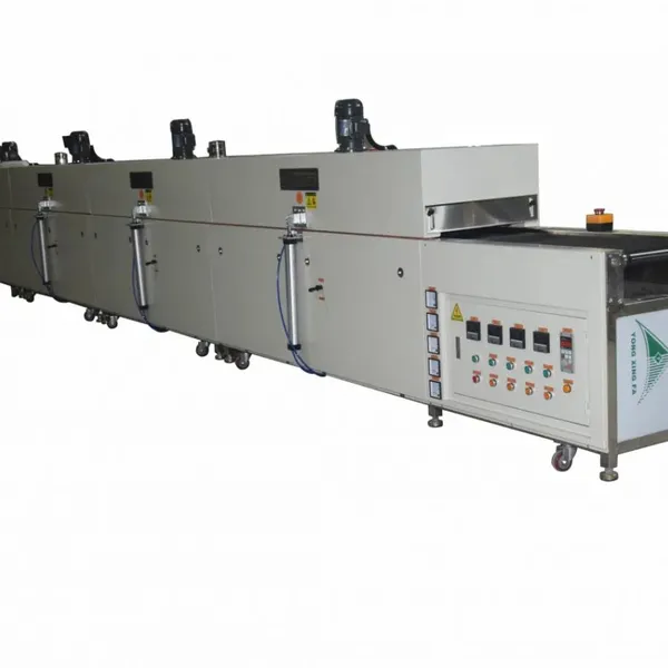
Industrial IR Tunnel DryerNegotiableMOQ: 1 Piece
-
Printing Drying Tunnel EquipmentNegotiableMOQ: 1 Set
-
Singapore pc Film Infrared Furnace Screen Printing Membrane Switch Tunnel DryingNegotiableMOQ: 1 Set
-
Paint IR Drying MachineNegotiableMOQ: 1 Set
-
Automatic IR Tunnel MachineNegotiableMOQ: 1 Set

-
Glass UV&IR Drying TunnelNegotiableMOQ: 1 Piece
-
uv Varnish Roller Spot Coating Machine for Wood is Designed for Smooth and EvenNegotiableMOQ: 1 Set
-
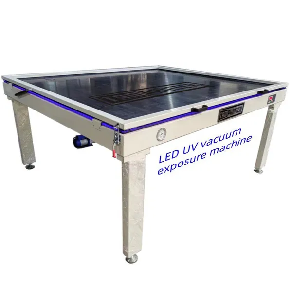
Customize Screen Printing Stencil Platesetter LED uv Vacuum Exposure MachineUS$ 4000 - 6000MOQ: 1 Set
-
ABS Enterprise Plastic Parts Vacuum Plating UV Light Curing MachineEUR 15600 - 16800MOQ: 1 Set
-
Ptfe Mesh Teflon in Fiberglass Ptfe Conveyor Belts for Tunnel Dryer MachineUS$ 200 - 2000MOQ: 10 Meters